: Main program body More...
Functions | |
| void | SystemClock_Config (void) |
| System Clock Configuration. | |
| int8_t | bme280_read_platform_spec (uint8_t reg_addr, uint8_t *rxbuff, uint8_t rxlen, void *driver) |
| int8_t | bme280_write_platform_spec (uint8_t reg_addr, uint8_t value, void *driver) |
| void | bme280_delay_platform_spec (uint8_t delay_time) |
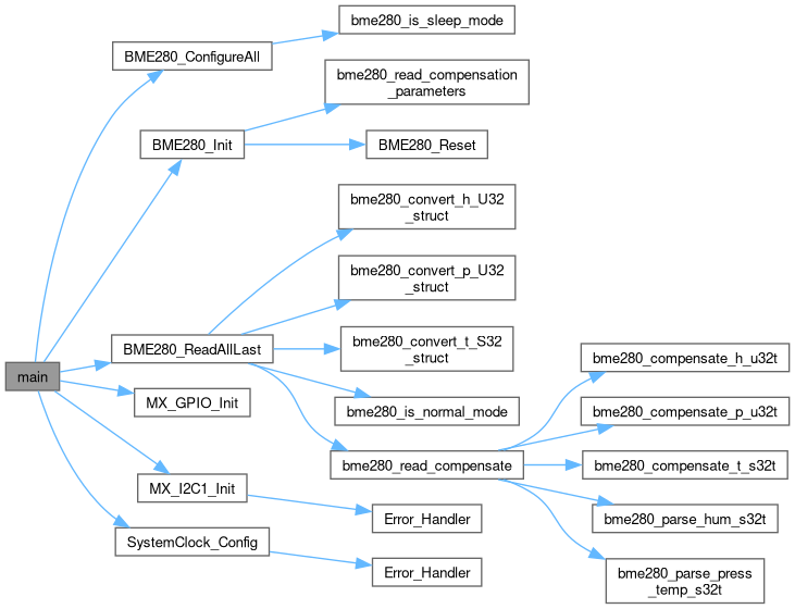
| int | main (void) |
| The application entry point. | |
| void | Error_Handler (void) |
| This function is executed in case of error occurrence. | |
Variables | |
| BME280_t | bme1 |
| BME280_Driver_t | bme1_driver |
| BME280_Config_t | bme1_config |
| BME280_Data_t | bme1_data |
Detailed Description
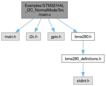
: Main program body
This is an example of use BME280_driver with STM32 platform and HAL library. There is one sensor connected to I2C1, pin SDO is connected to GND Results are stored as integers inside bme1_data structure. Sensor if initialized, then configured to work with normal mode. Last measured value is read every 500ms inside infinite loop.
Function Documentation
◆ Error_Handler()
| void Error_Handler | ( | void | ) |
This function is executed in case of error occurrence.
- Return values
-
None

◆ main()
| int main | ( | void | ) |
The application entry point.
- Return values
-
int
◆ SystemClock_Config()
| void SystemClock_Config | ( | void | ) |
System Clock Configuration.
- Return values
-
None
Configure LSE Drive Capability
Configure the main internal regulator output voltage
Initializes the RCC Oscillators according to the specified parameters in the RCC_OscInitTypeDef structure.
Activate the Over-Drive mode
Initializes the CPU, AHB and APB buses clocks